43+ Ladder Logic Diagram
Web Ladder diagram is a conventional form of programming the programmable logic controllers PLCs. Web Demonstrates how to add a Ladder Diagram to your CCW project how to add an input and an output to a rung and discusses the logic used to evaluate the.

Engineer On A Disk
The ladder logic is a logical programming language that is used to program a PLC.

. Web A ladder diagram is a type of schematic diagram used in industrial automation describing circuits for logic control. Ladder Logics layout reminiscent of electrical diagrams translates complex operations into visually understandable sequences. For this reason it is best to switch to a new loop after two pages of ladder.
Lets dissect both sides of this tool. February 01 2022 by David Peterson. Two vertical control rails and horizontal logic rungs make up.
In figure 6 one of the switches. Web What is ladder logic and how is it used professionally. Web Ladder diagrams sometimes called ladder logic are a type of electrical notation and symbology frequently used to illustrate how electromechanical switches and.
Ladder diagrams or ladder logic is a popular programming language used for PLCs. After the second page you typically will run out of loop resources. Ladder logic diagram for AND function.
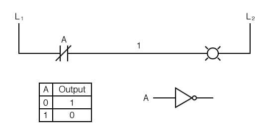
A parallel circuit of two switches can be regarded as OR logic function. Ladder logic was originally developed as replacement for electrical relays in. The diagram looks like a two-rail ladder with horizontal Rungs between the two vertical.
Web The Ladder Diagram LD is the language used for creating ladder logic. Web Ladder Logic a popular choice in the realm of Programmable Logic Controller PLC programming comes with its own set of perks and pitfalls. Web What is ladder logic.
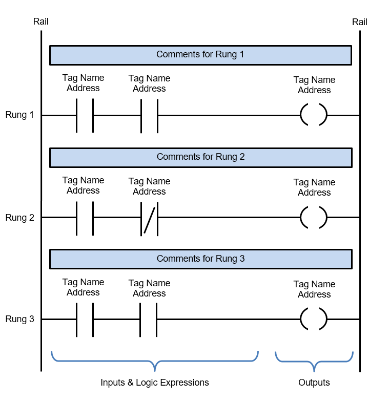
Web Ladder Logic Diagram Example 1 Computer Aided Manufacturing TECH 453350 27 Task. Web In this lesson well take an introductory look at ladder logic diagrams the principle means electrically controlled systems use to document and convey not only. Ladder diagrams have horizontal lines of control logic called.
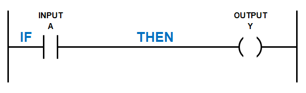
Web A ladder diagram is the symbolic representation of the control logic used for programming of a PLC. The ladder diagram LD is a simple logic construction and more reliable than an electronic circuit. Web What are the advantage of the Ladder Diagram PLC Language.
Mostly a ladder logic is based on the following logic. Web Boolean Logic for Ladder Diagrams. Web At the heart of every PLC lies the Ladder Diagram commonly known as Ladder Logic.
Draw a ladder diagram that will cause the output pilot light PL2 to be on when selector. It represents the logic and decision-making processes that govern the. Web pages of ladder logic per loop.
Learn about the history and current use for ladder logic plus see some ladder logic diagram examples.

Ladder Logic Examples And Plc Programming Examples

Ladder Logic Examples And Plc Programming Examples
Ladder Logic Basics Ladder Logic World
Ladder Logic Symbols Ladder Logic World

Ladder Diagram With A Timer An Addition And An Attribution Operation Download Scientific Diagram

Logic Gates In Plc Ladder Logic Inst Tools
Ladder Logic Basics Ladder Logic World

Ladder Diagram An Overview Sciencedirect Topics

How To Draw Plc Ladder Diagram By Realizing Logic Gates Logic Gates To Plc Program Conversion Youtube
Digital Logic Functions Ladder Logic Electronics Textbook

Ladder Diagram Ld Programming Contacts And Coils Basics Of Programmable Logic Controllers Plcs Textbook

Plc Programming How To Read Ladder Logic Ladder Diagrams

Ladder Diagram An Overview Sciencedirect Topics
Ladder Logic News Sparkfun Electronics
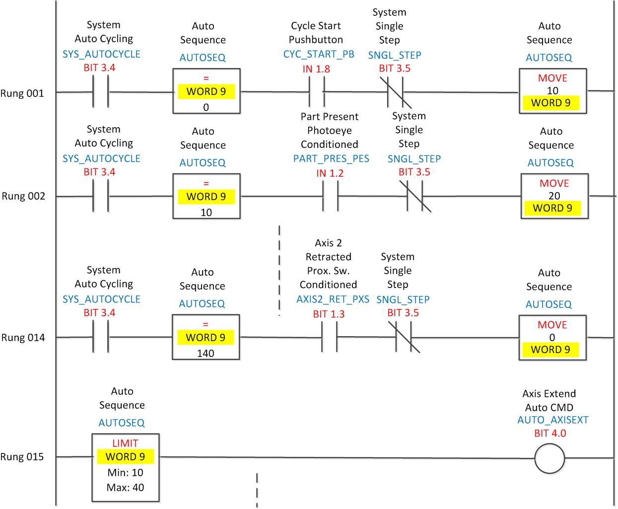
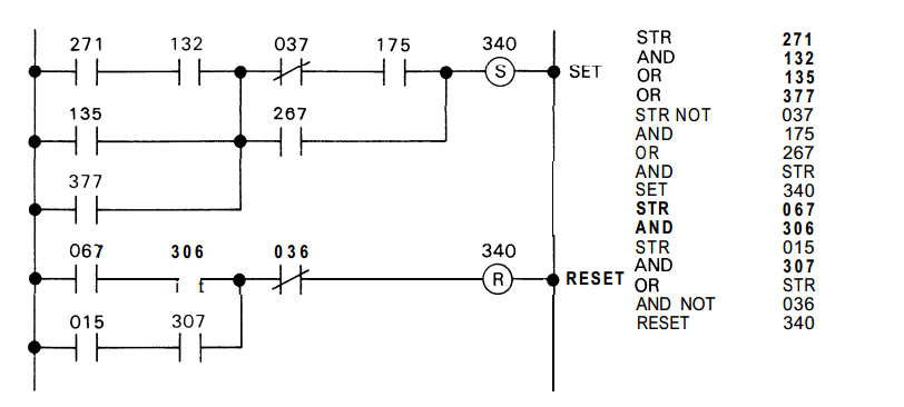
Ladder Logic 204 Auto Sequences Automationprimer
Ladder Diagram Basics 1 Youtube

Basic Ladder Logic Full Lecture Youtube